RISAFloor
will optimize
The Member Design Rules Spreadsheet records the parameters for the optimization. Optimization is performed for minimum weight, taking into consideration any depth, width, rebar limitations, etc. Note that the design rules input is one large spreadsheet, thus all of your design rules will be in the same place. Note that the dimensional rules and the reinforcement rules are all a separate entity. They have no interaction with each other in the program. They are simply all input into the same location. For example, your minimum member width rules will not be influenced by concrete beam reinforcement rules.
You can assign the design rules graphically as you draw or later as a modification. See Modifying Beam Properties for more information.
For additional advice on this topic, please see the RISA Tips & Tricks webpage at risa.com/post/support. Type in Search keywords: Redesign.
Note:
A Design List defines a set of member sizes that are considered when the program is suggesting member sizes. You may assign a Design List to a member based on Member Type. The design lists available for Column members may not match the design lists for Beam members, because some shapes are more appropriate for use as beams than as columns. You may edit these lists or create additional custom lists of your own. For more information on these redesign lists, including file format, editing procedure, and user defined lists refer to Appendix A - Redesign Lists.
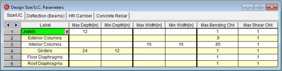
The Design Rules Spreadsheet records the limitations for the design and may be accessed by selecting Design Rules on the Spreadsheets Menu. You may create and name any number of design rules and assign different rules to various members.
The spreadsheet has four tabs: Size/UC, Deflection
You must assign a unique label to the design rules. You then refer to the design rule by its label when assigning it to members. The label column is displayed on all tabs of the spreadsheet.
You may enforce depth restrictions by setting either a maximum and/or minimum depth.
You may enforce width restrictions by setting either a maximum and/or minimum width.
Enter the maximum bending and shear unity checks. This should usually be specified as "1". If you desire a larger factor of safety, provide a lower factor (i.e. ".95").
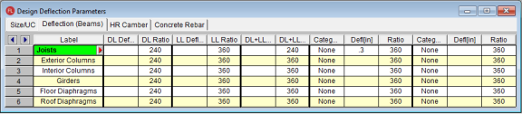
The entries for the Deflection tab are explained below.
Enter the maximum allowable dead load deflection and/or the minimum dead load deflection to beam length ratio.
If no redesign rules are assigned to a beam, then a default ratio of L/240 will be used for all shape groups except Steel Products and Wood Products which do not have a maximum DL Deflection Ratio.
Enter the maximum live load deflection and/or the minimum live load deflection to beam length ratio.
If no redesign rules are assigned to a beam, then a default ratio of L/360 will be used for all shape groups except Wood Products which have a default of L/480.
Note
Enter the maximum dead + live load deflection and/or the minimum dead + live load deflection ratio.
If no redesign rules are assigned to a beam, then no constraints will be used except Wood Products which have a default of L/240.
The remaining columns allow you to set deflection criteria for other load categories. Enter the category, the maximum deflection and/or the minimum deflection ratio.
For a cantilever the program uses 2*Cantilever Length in determining the L/ratio. For a 10’ cantilever that is deflecting 0.842” the ratio will be 2*10*12/0.842” = 285 (L/285).
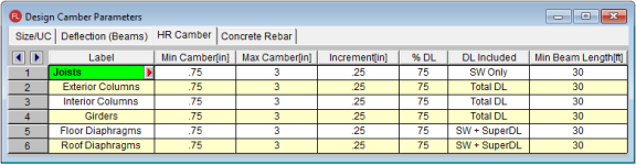
The entries for the Camber tab are explained below.
Enter the minimum and maximum camber values for the design.
Enter the cambering increment value.
Percentage of the selected load (see "DL Included") below to be considered for the camber design calculations.
Select the loading to be considered for the camber design calculation. Options include:
Enter the minimum beam length for camber design. Only the members that are equal to or exceed this length will be designed for camber.
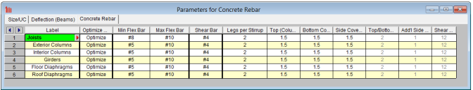
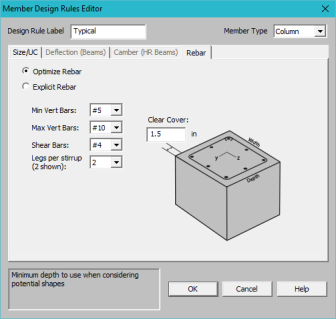
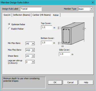
The entries for the Concrete Rebar tab are explained below.
Note
The options in this column are Optimize and Explicit. Optimize indicates the program will find the most optimal size and spacing of the reinforcement. Explicit indicates the exact number of and size of reinforcement bars. When Explicit is selected the additional columns are editable and allow you to enter the quantity for Top/Bottom Bars, Add'l Side Bars, and Shear Bar Spacing. These columns are greyed out when Optimize is selected.
Use the Min Flex Bar and Max Flex Bar columns to restrict bar sizes for your flexural reinforcing. Currently we support the ASTM A615 (imperial), ASTM A615M ("hard" metric, i.e. #8M is an 8mm bar), BS 4449 (British), prENV 10080 (Euro), CSA G30.18 (Canadian), and IS 1786 (Indian) reinforcement standards. You may specify your rebar set in the Model Settings - Concrete. You can force the program to analyze one bar size by setting the Min and Max values to be the same bar.
Use the Shear Bar column to enter the size of your shear ties. Currently we support the ASTM A615 (imperial), ASTM A615M ("hard" metric, i.e. #8M is an 8mm bar), BS 4449 (British), prENV 10080 (Euro), CSA G30.18 (Canadian), and IS 1786 (Indian) reinforcement standards. You may specify your rebar set in the Model Settings - Concrete.
Use the Legs per Stirrup column to enter the specific information about how may legs (2 to 6) each of your shear ties is expected to have.
The last three columns are used to specify the clear cover measured to the shear reinforcing. Note that the Top Cover is used for all sides of Column members.
The Member Design Rules Editor provides a way to create or modify member design rules in a graphical way. This editor automatically updates any information input into the Member Design Rules spreadsheet.
Note:
Keep in mind that this dialog has
The Design Rule Label is editable and will change the spreadsheet label. It is useful to name the design rule with a descriptive name like "First Floor Columns".
The Member Type listed is for reference of the picture only in this dialog. The member type will not control the Member Type of the beam or column which you will need to assign separately when the member is drawn.


This only applies to Beam members.

This only applies to Beam members.

You can select Optimize or Explict to set the rebar design parameters.
To access this editor you can click the

The member redesign dialog allows you to select one member at a time to view the current beam size, redesign rules, and calculated code check limits. You may then interactively select another size for investigation and instantly see the new calculated code check limits. If you are happy with the new size you may then apply that new size to the member.
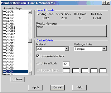
To Perform a Member Redesign
Assumptions of the Redesign Dialog
The member Redesign Tool is intended to allow the user to assign a specific shape to their beam after the solution is run. For composite beams, the amount of studs may also be adjusted in this dialog.
The Redesign dialog optimizes the beams creating a list of shapes using the following assumptions:
When a user makes a change in the Redesign dialog, the following occurs:
Note